Assembly
It's time to build a robot.
It just time. Software is no fun anymore. AI has basically taken all of the challenge out of the endeavor, and its frankly not all that impressive to be able to do it.
Perhaps, EA was right all along, I am just looking for a sense of pride and satisfaction in the work that I do. And therefore, I need to leave virtual world and build something in the physical world.
Call its Frankenstein's dilemma. I may not particularly like AI, and I worry that it has cheapened the human endeavor, but I cannot ignore its creation, no matter how monstrous it is. So I will build a robot that is powered by AI. My basic idea is that I will start by building an RC car with a Claude running on a raspberry pi to control its movement.
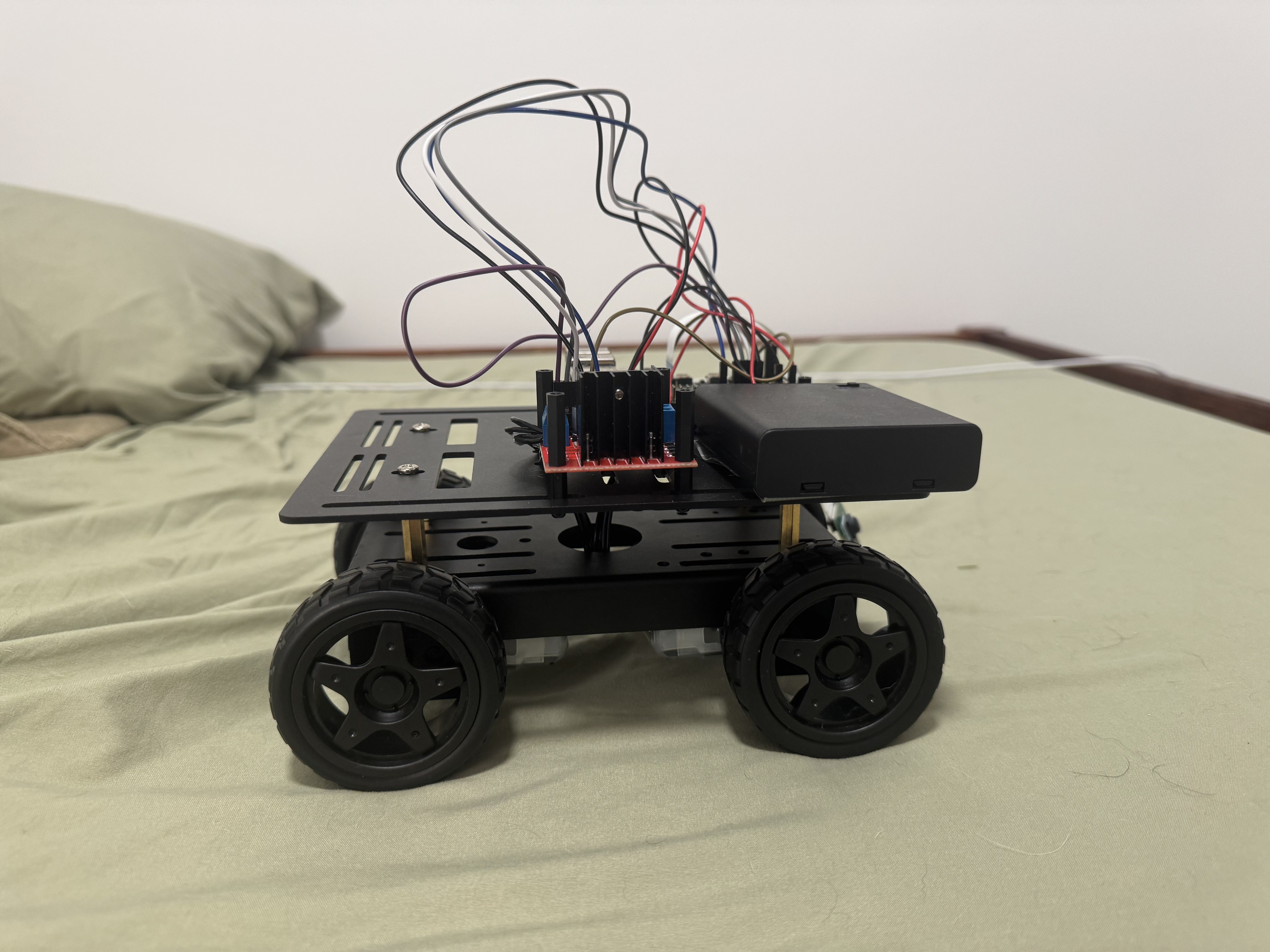
List of materials
As with all my projects now, I started by asking Claude what I will need to get things done. It came back with this list:
- LewanSoul 4WD Smart Chassis Car Kit - this will be the platform upon which I build the car
- Arducam for Raspberry Pi - eyes for my robot to see
- L298N Motor Driver Controller - serves a bit of a bridge between my raspberry pi and the motors that actually drive the car
- 6V AA battery holder - these will actually power the motors in the wheels
- Stand off spacers - creates some separation from the aluminum chassis for the raspberry pi.
- Female to Female and Male to Female Breadboard jumper cables - Claude actually messed this up and said I only need male to female, but you need both
Assembly
Putting this together was equal parts surprisingly easy and extremely challenging, and, (spoiler!), all the challenges arise from using the LewanSoul kit. Let me set out what I need to do. We are going to wire the motors from each wheel into the L298N and then wire that into the Raspberry Pi.
Sounds simple, but here is the trouble. For the LewanSoul kit, the wires coming off each motor are capped with something called JST connectors, which are meant to plug into JST female sockets. But, the L298N does not have JST female sockets. Instead, it has screw terminals, so I needed to cut off the connectors and use a wire stripper to get down to the bare wires.
Once I have each wire stripped, I can then shove them into the screw terminals and screw them into place. This is annoying for two reasons. First, I do not like conducting an unreversable operation like snipping off connectors and exposing the raw wire with a wire stripper. That scares me.
Second, each motor effectively has two wires coming off of it, and they are not color coded, so you simply need to guess which is which. This combined with each wire being very short, and you an incredibly obnoxious build process.
Crossed Wires
Things are about to get really hairy, so I am going to explain this as best I can, but an electrical engineer would have to correct me. After you cut the JST connector, it will look like you have eight different wires or two for each motor. But you actually only have four.
Within each motor is a coil of wire called the rotor, which sits between two permanent magnets. When current flows through the coil of wire, it becomes an electro magnet and the pull of the magnet spins the wheel. The two wires you see coming out of the motor are actually two ends of coiled wire that makes up the rotor.
The direction of the current that flows through the coil determines which end becomes north vs south, which in turn determines which way the wheel will spin.
With an L298N, you choose which of the screw in terminals are positive and which is negative. Electricity will flow from the positive terminal into the negative terminal, also known as the ground. It will need to flow through the wire (and the rotor) to do that. Imagine that you unspooled the rotor and laid it out as a straight wire and labeled one end x and one end y.
If you plug in the x wire from the front left motor into the positive terminal and the y wire from the back left motor into the positive terminal than they would spin in opposite directions because the current is flowing through the wire in opposite directions.
As I said, the issue is that the wires are not labeled, so unfortunately, I did exactly that and the wheels spun in opposite directions.
After about an hour of trying to shove these tiny little wires into an even smaller little space, the wheels finally spun the correct way, and I was quite pleased.
Here is the final wiring table:
| Motor | End of Wire | Screw |
|---|---|---|
| A (Front Left Motor) | X | OUT3 |
| A | Y | OUT4 |
| B (Front Right Motor) | X | OUT1 |
| B | Y | OUT2 |
| C (Back Left Motor) | X | OUT3 |
| C | Y | OUT4 |
| D (Back Right Motor) | X | OUT1 |
| D | Y | OUT2 |
Connecting L298N to Raspberry Pi
Now, there is quite a few jumper cables running between the Raspberry Pi and L298N, and as you can imagine, they each have their own job. I mean look at this mess:
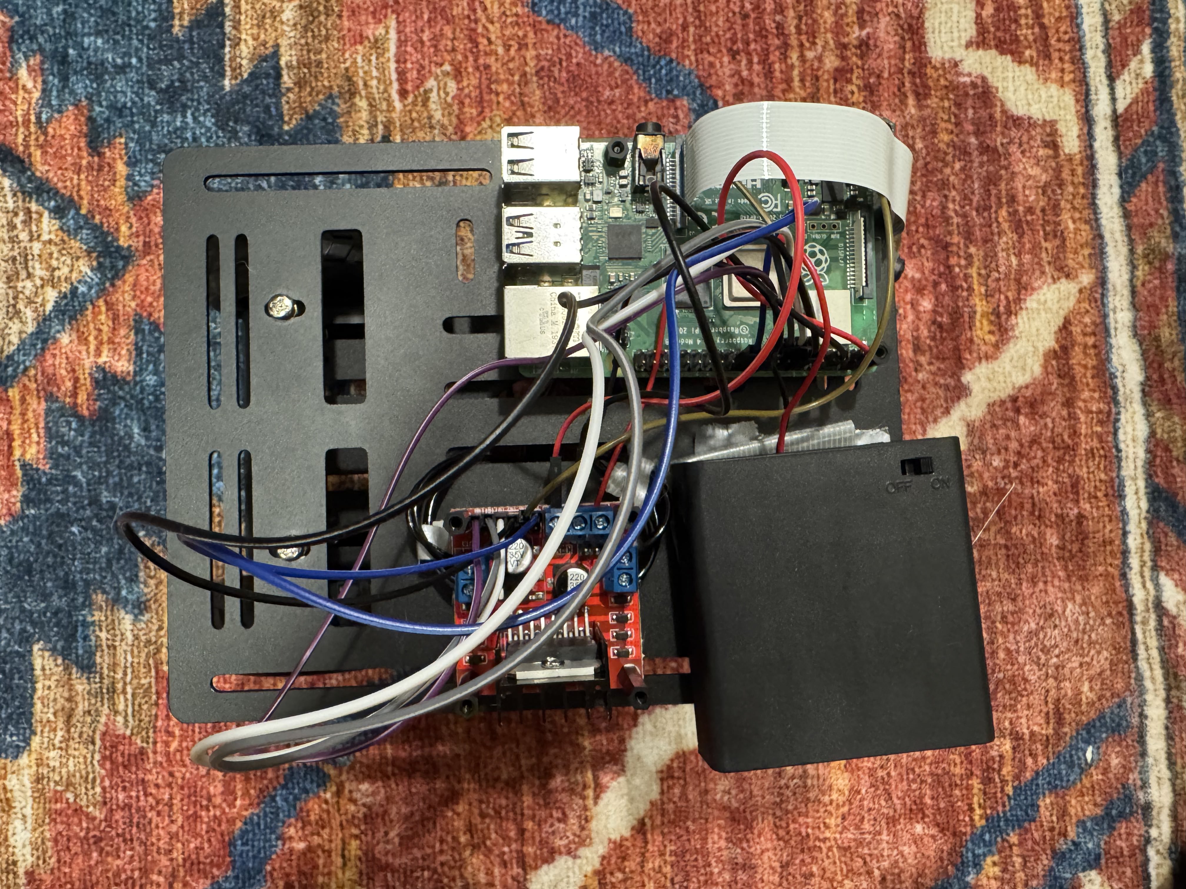
But what each cable does actually all comes down to the pins on the L298N.
| Pin | Use |
|---|---|
| IN1 | When it is set to high, it makes OUT1 positive |
| IN2 | When it is set to high, it makes OUT2 positive |
| IN3 | When it is set to high, it makes OUT3 positive |
| IN4 | When it is set to high, it makes OUT4 positive |
| ENA | When set to high, current runs through IN1 and IN2 |
| ENB | When set to high, current runs through IN3 and IN4 |
So, like we said earlier, the direction the current runs through the wires determines the polarity of the rotor which choose the direction of the wheel's spin. When IN1 is set to high, the current runs from OUT1 through the wires into the rotor and then back out through OUT2, which causes the wheels on the right side to spin forward. The same is true of IN3 for the left side motors.
Now for the raspberry pi side of the equation. It comes with 40 pins, which you can plug jumper cables into. Most of them are entirely programmable. You choose what they do in software.
Now here comes an unnecessary complication. The pins physical position is traditionally read left to right top to bottom— with the top left pin being 1 and the bottom right pin being 40. But for some god forsaken reason, in software they are assigned GPIO numbers that are slightly different than their physical position. Apparently this is based on the chips internal wiring, but man is it stupid.
Anyways— this is how we chose to map them:
| Raspberry Pi Pin | L298N Pin |
|---|---|
| Pin 11 (GPIO 17) | IN2 |
| Pin 12 (GPIO 18) | IN1 |
| Pin 13 (GPIO 27) | IN4 |
| Pin 15 (GPIO 22) | IN3 |
| Pin 18 (GPIO 24) | ENB |
| Pin 22 (GPIO 25) | ENA |
In software, we will assign our raspberry pins to the IN pins on the L298N based on how we plugged in our cables. So if we want to move the car forward, we will set IN1 to high by sending a high signal through Pin 12 on raspberry pi and a low signal through Pin 11 to IN2. We will cover this in more detail on the next part of this series, where we cover the python script.
As I mentioned earlier, they are not all programable. Pin 2 produces 5V of power, which will be used to power the L298N chip. That must go into the 5V screw. Pin 6 is a ground, and that must go into ground screw on the L298N board.
Finally, we need power for the wheel motors. We will use four AA batteries. This time we will put the red cord out of the AA batteries in the 12V screw and put the black cord into the common ground (which also holds the ground wire from the raspberry pi).
Wow, look at you. You just learned a little bit of electrical engineering. Next stop: a sweet gig at Nvidia.